
Analysis
Requirements
-
Suspension must be able to support 6 pounds with a ride height of 2 inches
-
chassis can’t weigh more than 6 pounds
-
Chassis must not deflect more than 1/8in during the drop test.
-
Suspension must allow for at least .5 inches of drop when dropped from 2 feet
-
Chassis must be small enough to not interfere with full range of wheel turning motion giving .25 inches of clearance from chassis
-
Can’t total more than $200

Analysis 1 consists of force calculations on 1 leg that can be reflected into all others. Calculating average shear around the cross-section area of the hole. Using a stress concentration graph to obtain a K value of 2.2 and multiplying it by the average shear to obtain the max shear around the hole.
Analysis 1
Analysis 2 consists of a kinetic energy conversion from the 2-foot drop to determine the force once impacting the ground. From there the inertia of a 18 in long 12 in wide and a height of .25 in plate being used at the foundation of the chassis is calculated. This value is plugged into a beam deflection calculation in order to determine the Ymax of the deflection.


Analysis 2
Analysis 3 uses conservation of energy and Hookes Law in order to determine the spring constant, K, of the shocks. Using the drop height to calculate the energy generated by the force of the fall and then calculating the K using Hookes law. using this determines the spring capacity needed on an adjustable 4 inch shock desired for the design.
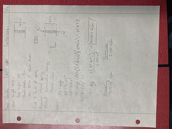
Analysis 3

Analysis 4 consist of a geometric analysis in order to determine the dimensions of the shock tower. These dimensions were determined using Pythagoras theory in order to determine the length, L, of the tower wings that support the shocks.
Analysis 4
Analysis 5 is a minimum diameter analysis of the pin being used between the chassis and the A-arm in order to hold the 2 parts together. Using the known max sheer value, the force on the pin and the safety factor the minimum value is determined and then rounded to the nearest manufacturable value.

Analysis 5
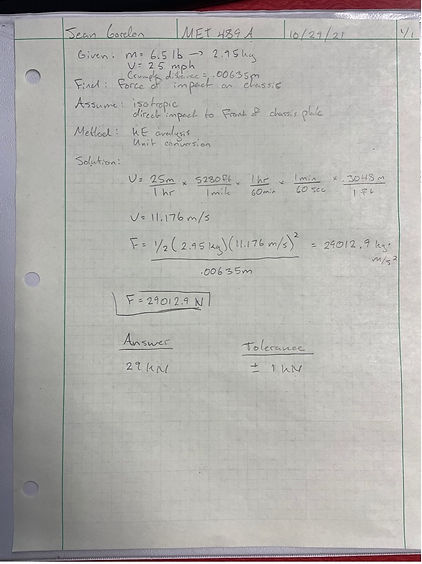
Analysis 6 is a crumple distance analysis where the force on the chassis in case of a direct impact to the chassis takes place where the force of the impact is determined. Using the assumed maximum velocity, the mass of the car and the material of the chassis to determine the force on the car will be 29kN resulting in a crumple distance of .00635m.
Analysis 6
Analysis 7 is a shear stress analysis for the screw being used to attach the shock tower to the chassis plate. This is done using a shear stress equation and rearranging for the diameter of the part. Once done, using the known values of the material and a safety factor of 2.5 the minimum diameter required is determined and the next largest manufactured size can be selected.
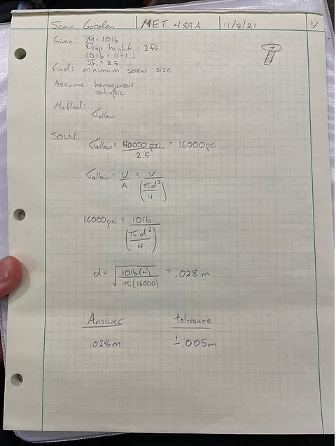
Analysis 7

Analysis 8 is a maximum angular velocity calculation that must be done in order to determine the torque at the end of the suspension leg. This is done using unit conversation to get from miles per hour to meters per second, then Using an angular velocity equation with the determined radius of the wheel the maximum angular velocity can be found.
Analysis 8
Analysis 9 is a minimum suspension arm thickness in order to support the impact of the drop test. this analysis is done by calculating the moment of the impact at the end of the arm then using the known max shear stress of the material solve for thickness assuming the minimum thickness modeled in the arm is the value throughout the arm for safety.

Analysis 9
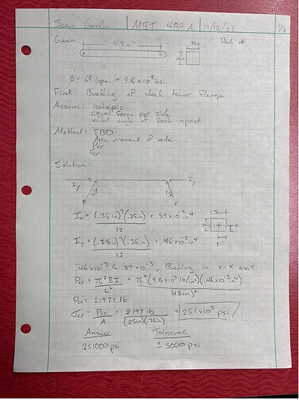
Analysis 10 is a buckling analysis on the flange of the shock tower. This analysis is done by calculating the area of inertia in both the x and the y directions in order to determine the buckling direction. Once determined the critical force is calculated with the buckling along the x-x axis and used to calculate the critical sheer force of the flange.
Analysis 10
Analysis 11 is a shear calculation on the A-arm of the car experiencing the maximum amount of shear capable of being applied by the motor. This is done by using the known power output of the motor with an assumed efficiency of 85% and the angular velocity of the tire calculated in analysis 8 to determine a torque for the calculation. Then at the end of the A-arm in the location with the smallest area a sheer force of 146.2 psi is calculated to take place.
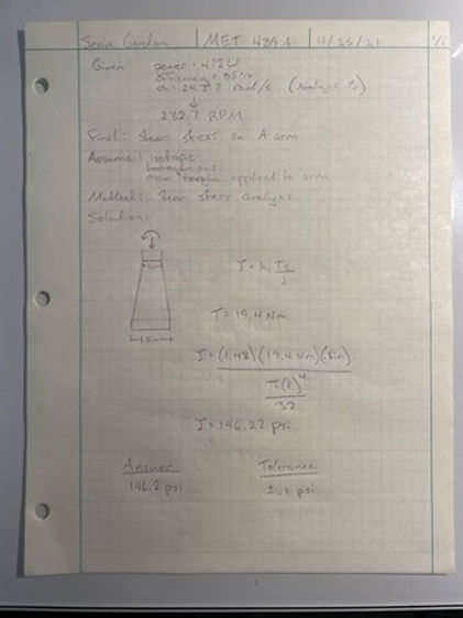
Analysis 11

Analysis 12 is a trigonometry calculation that is determining the angle of rotation that takes place in the A-arm to chassis joint. Using the maximum compression distance determined by the success requirement it is determined that an clockwise rotation of 9.6 degrees from the X axis will result in the maximum rotation required for the joint.