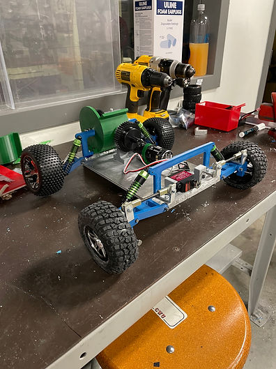
Construction
This device is broken up into 2 sections, the chassis and suspension. The chassis sub assembly is made of 5 parts. The foot pin connects the foot to the A arm the A arm is connected to the chassis base plate by a pin. The second sub assembly is the suspension. This assembly consists of 2 parts including the shocks and shock tower. These 2 sub-assemblies are bolted together to create the final assembly. Most of these parts will be manufactured in the CWU lab. The only component that will be bought from a manufacturer and won’t receive modifications before construction will be the shocks. The chassis base plate, feet, and A-arms will be manufactured from the same stock material while the shock towers will have a thinner material to be cut from. The pins will be cut from the same round to reduce material and manufacturing costs.

Manufacturing of PIN - CONNECTING, A-ARM, STEERING (SAG_20-004) began with cutting .25 inch rounds into 1.5 inch long segments using a metal cutting miter saw. Then, each of those segments was cleaned up with a general purpose metal file in order to fit into chassis hole by removing excess material left behind from cutting.
Figure 1
Manufacturing of CHASSIS - BASE PLATE (SAG_20-001) started with .25 plate aluminum cut by a plasma cutter with a programmed outline. From the sections cut with the plasma cutter the supports were welded to the larger plate as seen in figure 2. The edges were the filed to create a smooth alignment between supports and plate for the installment of the pin holes. Those holes were added using a drill press while clamping the plate down to ensure accuracy. The final step was adding the fillets using files increasing in grit to ensure an accurate radius to the pin holders to allow for smooth rotation of the A-arms around the chassis base plate

Figure 2

Manufacturing of PIN - CONNECTING, A-ARM, STEERING (SAG_20-004) required cutting from a large piece of .25in stock material to make a more maneuverable piece of material to manufacture into the 4 smaller identical parts.
Figure 3
Manufacturing of CHASSIS - BASE PLATE (SAG_20-001) requires the addition of .25in holes for the A-arm pins to be attached. These holes are added using a drill press and clamp combination to hold the chassis plate in place. Once the location is marked a lubrication is added to the drill bit to prevent excess heat while drilling and 4 holes are added to the chassis.
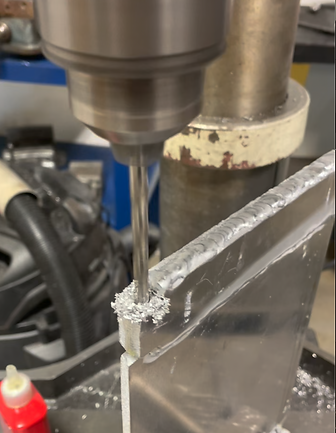
Figure 4

Manufacturing of CHASSIS - BASE PLATE (SAG_20-001) required the usage of the CWU lab plasma cutter to remove the basic outline of the chassis and supports from the larger stock material, a plate of .25in aluminum. This provides an outline that can be worked with smaller tools into the determined tolerances of the part.
Figure 5
Video of Construction
Summary of video
This video is a presentation of the manufacturing techniques used to develop parts for this project primarily focusing on the chassis plate production. Initially starting with a video of the plasma cutter cutting out the basic shape and support of the plate. Next, the video shows 2 different angles of the welding being completed by CWU lab tech Bo Nielson attaching the supports to the chassis plate. Following those 2 videos is a video of the drill press being used to create pin holes for the A-arms in the side of the chassis base plate. the remaining 2 videos covering the chassis plate include filing and sanding the edges to fit the tolerances determined as discussed earlier in the construction process. The final video displays the metal miter saw, which was used to cut from the stock .25in round creating the A-arm pins.
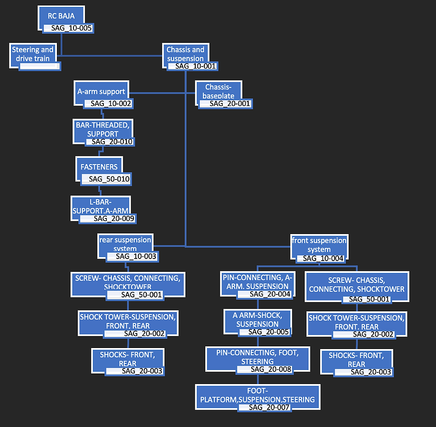
Drawing Tree